- IN 2024, ARKANCE WILL REVEAL A FRESH NEW LOOK FOR ITS BRAND IDENTITY, MARKING AN IMPORTANT MILESTONE IN OUR INNOVATION JOURNEY AND COMMITMENT TO SERVICE EXCELLENCE.


Have you ever wondered what it takes to create a family in Autodesk Revit from scratch? You may say it’s easy. Just select a template and get going with work. Some other person maybe confused where to put the reference planes. Then the third guy comes and tells everyone to just forget it all and download the family.
But what if you don’t get a desired family of your choice on the internet? What if, even after you find the a family of your choice, its size is so much that your PC crashes each time you load it into the project?
So, when you have to create your own Revit family, follow the 5 steps mentioned below which will he you in modelling.
1. Choose the appropriate template
Just like a correct template is required to start a project, similarly a correct template (.rft) must be used to start a family. The significance of template becomes most important when it is in reference to category of the family. Furthermore, in the template few features are created for you to easily model the specific geometries.
For Example, a structural column family template will have Depth and Width parameters to begin modelling the column, thus saving time and effort

2. Place reference plain and create parameters
It is always good practice to place reference plane and add parameters to the reference planes (Dimensions parameters) and then flex the reference planes to see if everything is in sync or not. Often people make the mistake of creating geometry first and then creating the reference planes. The former should be followed for seamless workflow while modelling Revit families.
It is utmost important to flex the parameters so that you become doubly sure whether or not the parameters and reference planes are attached to each other.

3. Create geometries and lock them to the reference planes
Geometries in Revit families can be created by using the following methods:
• Extrusion: is a sketched shape pushed along a distance perpendicular to the sketch plane.
• Blend: 3D form is Created by Blending a top and a bottom shape placed perpendicular to each other
• Revolve: Spins a Sketch Shape around an axis.
• Sweep: Pushes a Shape (sketch or loaded profile) along a sketched path. The shape is perpendicular to the path.
• Swept Blend: Combines features of both the blend and the sweep.
After creating these geometries, you need to lock the geometries to the reference planes and work planes. The best way is to lock geometries to the reference planes is to use ALIGN command or the AL short key.
Pro Tip : A reference plane becomes a work plane when it is named. After this it will show up in the SET PLANE drop down list.

4. Associate visibility and material parameters to the object
When the object is created by a combination of the modelling commands, each geometry can be selected separately and given a material. Once this material is applied, then it cannot be changed when loaded into a project.
For changing the material from inside the project, you must associate the material parameter in the family editor itself as shown below.


Similarly, when we want to control the visibility of an object, we need to associate the Visibility Parameter of the object. This way you will be able to control whether the object is visible in the project or not with a simple checkbox.
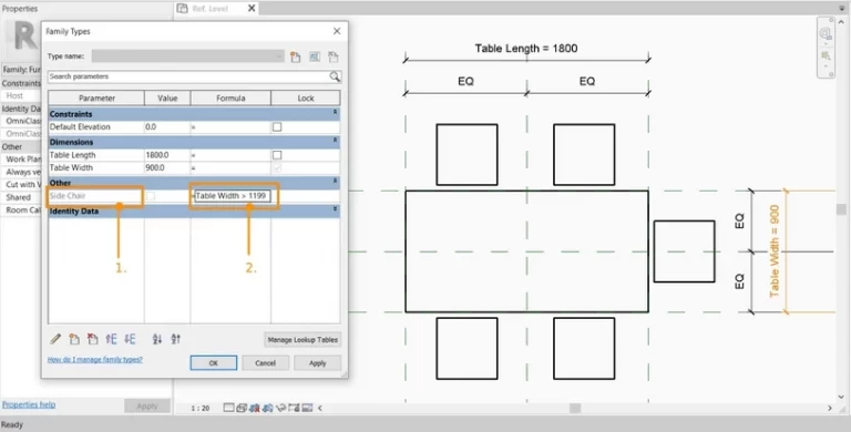
Pro Tip: Control the visibility of objects based on a formula
Eg: If you consider a dining table set, there will be chairs along the length. You may want to add a chair along a width when the width exceeds a certain value. Use the formula against the visibility parameter say, Width of Table > 1200mm.
5. Create family types
When your family is ready, you can create family types. Family types can be created for fast and efficient use in the project.
Eg: A dining table family can have a 4-seater option, 6-seater, 8-seater and so on. Then you can create types of that family and use it in your project.
